Preliminary
Let me begin with an example, which is well known by everyone. It is the public lighing. Its scheme is show below.
At sunset, when it is becoming dark, the public lighting turns on, and when the sun is rising, it turns off.
The sunshine is sensed by a light sensor, which serves an electrical signal propotional to the ambient light intensity. When this electrical signal falls below a certain point, the measuring unit decides to turn on the lights.

Public lighting scheme
In this article I will focus on the sensor’s inside, how it works, and what if we want to measure other types of physical properties, eg. pressure, temperature or rotation.
Normally, a sensor (transmitter show non the picture below) needs supply voltage, which means 2 wires, and provides an output, which needs an additional wire. This way a sansor is connected to the measuring unit through a 3 wire cable.
One option for the transmitter is to generate a voltage at its output. This output is in linear relation with the measure physical value.

3 wire, voltage output transmitter
Other option is to generate a current output, which lacks the voltage divider, and noise issues. Current based signals can be transmitted over much longer distances compared to voltage signals.
The most common current signals are: 0-20 mA and 4-20 mA currrent loops. These signals usually flow through a resistor. This way a voltage is present at this resistor, and the A/D converter measures this voltage.
The huge advantage of the 4-20 mA signals is the possibilitiy to detect cabling errors. If the measured current is 0 mA, then one of the wires is disconnected.
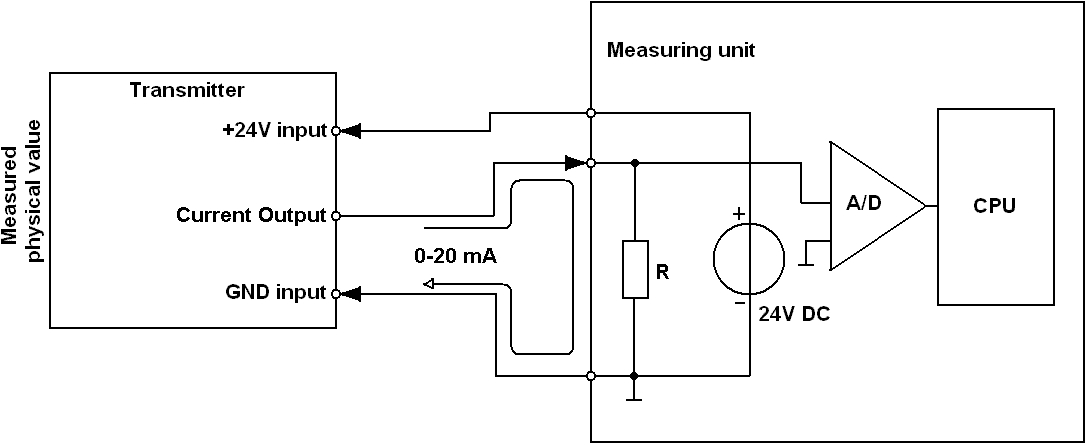
3 wire, current output transmitter
3 wire transmitter electronics
At first, let’s see a simple light measuring circuit.
 3 wire, light input, voltage output transmitter inside
U1 can be LM324, and D1 is SFH203.
The photodiode senses the ambient light, which generates a current flow through it. This current goes into an active current-to-voltage converter formed by U1B. The output of U1B is simply amplified by U1A to generate a 0-10 V signal propotional to the light intensity.
If this light transmitter generates a current at its output, then a voltage to current converter must be applied as shown below.
 3 wire, current output transmitter inside
The simplest voltage to current converter consists of an operational amplifier (U1), a MOSFET (Q1) and a current sense resistor (R1). The op. amp gets the control voltage (0-2V) to its noninverting input and drives the MOSFET until the voltage across the sensing resistor exactly matches the input (control) voltage.
 Pure, high side 0-20 mA transmit circuit
Possible choice for U1 is LM324, for Q1: Si4410.
A few additional elements must be added to the circuit for improved protection and stability. D1 protects against overvoltage, R2 reduces the op. amp’s capacitive load, while C1 slows down the regulation loop.
 Analog input, high side 0-20 mA current loop transmitter
U1: LM324, Q1 Si4410, D1: 1N4007.
The main disadvantage of the upper two circuits is that they generate „up side current”, so the load resistor (RL) cannot be grounded.
Some modifications must be made to solve this.
 Analog input, low side 0-20 mA transmitter schematics
U1: LM7322, Q1: Si4410, Q2: Si4431
The schematics shown above illustrates this „trick”. The input voltage is referred to ground. With U1A, Q1 and R1-R2-R3, this voltage falls across R1, but now it is referred to the positive power supply voltage. This voltage controls U1B (the voltage to current converter) which then generates a corresponding output current. R1, R2 and R7 must be tight tolerance types (0,1% or better) to achieve high accuracy.
An alternative of this circuit is made of a difference amplifier, but the principles are the same.
 Alternative, analog input, low side 0-20 mA transmitter schematics
Current loop receiver circuit
Just a few words about the current loop receiver circuit: the measured current flows through a resistor (R1) thus a voltage is present at the input of the op. amp. The capacitor (C1) is for high frequency attenuation, Z1 zener diode limits the maximal voltage across the resistor, protecting the additional electronics this way.
 Analog output 0-2 V, resistor based, 0-20 mA receiver circuit
Z1: 2,7V zener, for maximal precision R1 should be 0,1% tolerance.
2 wire transmitter electronics
The wiring cost can be high if the distance between the measuring unit and the transmitter is long. We could reduce this if we use 2 wires instead of 3. This scheme is called 2 wire current loop, where 2 wires carry both the power and the measured signal. Its standard signal level range is 4-20 mA.
Staying with the light measuring example, if we sense no light the transmitter consumes 4 mA, while, at midday, at full sunshine it consumes 20 mA. So the actual current flowing through the transmitter is propositional to the measured physical value.
 2 wire, 4-20 mA transmitter connection
The picture below shows the very basic components needed to form a 2 wire transmitter.
U2 is a linear regulator, it produces a fixed voltage to the internal electronics. U1A buffers the measured input voltage and drives U1B through R1. R2 creates the 4 mA initial current, R3 senses the output voltage (propotional to the output current) that falls across Rsense. Q1 is actually the current generator element.
 Basic, analog input, 2 wire, 4-20 mA loop powered transmitter
U1: MCP617, U2: LP2950, Q1: BD139, D1: 1N4007
The simplified equations for this circuit are the followings:
For 0V input (4 mA output current): Vs / R2 = 0.004 * Rsense / R3, where Vs is the internal supply voltage (5V shown in the picture above).
For 5 V input (20 mA output current): Vinput / R1 + Vs / R2 = 0.020 * Rsense / R3.
The simplification is based on: R3 >> Rsense.
In order to calculate its elements’ values, some initial conditions must be settled.
We must choose the values of Rsense, R3 and Vs.
For example let Rsense be 10 Ω, R3 = 10kΩ and Vs = 5V, with these values all the other componets can be determined.
Care must be taken to choose a low quiescent current type linear regulator (U2) and low power, single supply, dual opamp (U1).
With all these informations, let’s see how a rotation to current transmitter looks like inside.
 Potentiometer input, full analog, 2 wire, 4-20 mA loop powered transmitter
B1 is a simple diode bridge, it is for reverse voltage protection.
Setup: turn P1 to the lowest position, then set P3 in order to measure 4 mA in the current loop.
After this, turn P1 to the highest position, then set P2 to make 20 mA flow in the loop.
With this, turning P1 casuses current flowing linearly propotional between 4 and 20 mA.
If you want reduced potmeter travel (for example not the entire 270˚ rotation, just 90˚) repeat the 4 mA setup (shown above), then set P1 to 90˚, and then adjust P2 to measure 20 mA in the current loop.

Dear. I’m trying to build the circuit “Potentiometer input, analog full, 2 wire, 4-20 mA loop powered transmitter.”
You built this circuit? If this is correct, it could send the resistor values I use?
One last query: have any armed simulation in some livewire program like or similar?
Again, thank you very much and very interesting information!
LikeLike
“You built this circuit? If this is correct, it could send the resistor values I use?”
I only built the simplified version of this circuit, which was working fine, the schematic shown in the post clearly describes the operating principles.
Send the resistor values and probably I can help you.
“have any armed simulation in some livewire program like or similar?”
I haven’t done such thing…
LikeLike
Hello! Could you please explane why do we need D1 in 2-wire 4…20 mA loop scheme? As i understand, it will fix the voltage on the Rsense and current will also be fixed?
LikeLike
Hello Mikhail!
D1 is just for limiting the voltage drop across Rsense, but normally doesn’t do anything. With Rsense = 10 ohms and Iloop = 20 mA, the voltage across Rsense is 0.2V, but until 0.7V the D1 diode act as an open circuit.
LikeLike
D1 limits the voltage across Rsense, but what PURPOSE does D1 serve? Is it there to limit the overall current? If so, that limit will be very temperature dependent.
LikeLike
The voltage at U1B’s non-inverting input is limited (at approx. Vss-0.3V), by using D1, is remains at safe limits at all time (during powering ON the circuit).
LikeLike
what is the U1 part number for Current loop receiver circuit?
LM321?
LikeLike
Of course LM321 is acceptable, but any op amp with voltage sensing capability down to 0V is fine. Keep in mind that it is a measuring circuit, so the less the input ofset voltage the better.
LikeLike
Hi, Thanks for the great information, I have few doubts w.r.t 0-20mA low side driver:
1.In earlier circuit, we can determine the current by calculating 2/10K = 0.2mA for a 2 volt input. In this circuit, how can we find a relation between the current through RL (load) and the R2(10K)
2. As you mentioned in the description, R3 100 Ohms is to reduce Op-Amp capacitive load , but we are adding another cap of 100pF at the output of Op-Amp; doesn’t this act as another capacitive load? Does adding capacitor at the output of OpAmp affect stability?
3. As you said the purpose for R3 and C1; can you specify the purpose for R4
Thanks in advance for your inputs
LikeLike
Hello
1. The current through R2 (Ir2) is: Ir2 = Uin / R2.
Ir1 = Ir2, because they are connected in series.
Ur1 = R1 * Ir1 = Ur7 = Iout*R7
Iout = Iload.
So as long as R1 = R2, Iout = Ir2 * R2/R7.
2. yes, the 100pF capacitors improves the stability, because they are in the feedback loop so they slow down the op amps to prevent ringing, additionally C1-R4 and C2-R6 acts as a low pass filter.
3. see answer 2.
Hope this helps.
LikeLike
I think there’s a mistake in the alternative differential low-side circuit (0_20ma_low_side-transmit_2.gif). The 0-2V should go into + of U1A. Since the supply is not bipolar and the 0-2V is fed to the -, the amp will only output 0V. Not sure if C1 & R2 should connect to 24V or ground.
LikeLike
R1 and R2 acts as a voltage divider, so U1A+ = 12V, thus U1A- = 12V, the rest can be calculated…
LikeLike
The first analog low-side circuit (2014/07/0_20ma_low_side-transmit_1.gif) above works great! I was wondering if I could also use this circuit for low current output for simulating sensors (nA and uA range). I replaced R7 with a 1M resistor, however, the output is zero below 0.4V, linear up to 1.1V, then highly non-linear above 1.1V. The linear range would need software calibration since the numbers don’t correlate. Is there a simple change that could be made to make perform like the 4-20mA circuit?
Thanks!
LikeLike
Try omitting R2 and C5
LikeLike
The first low-side transmitter above has no C5. R2 should be shorted or opened?
LikeLike
Sorry, on the first low side transmitter: C2 and R5, R5 should be shorted, C2 omitted.
LikeLike
Thanks for the response and the great articles!!!
LikeLike
you are awesome works perfectly
LikeLike
Thank you very much!
LikeLike
Q1: Si4410, Q2: Si4431
hard to find 😦
LikeLike
Any MOSFET with similar specs will do the job.
LikeLike
Can you explain the function of D1 in the high-side and low-side 4-20ma circuits above?
LikeLike
It is just for protection.
LikeLike
From voltage spikes on long loop cable?
LikeLike
And protection from external voltages at the output.
LikeLike